Building an Input register Pt 2
Having built my keyboard See here. I went on to build the actual input module.
Firstly here are the parts I intended to use (the final design is different!)
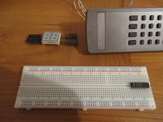 The list is 1 x 74C922, 2 x AM2918 Russian clone 2 x DM9368 hex to 7 segment driver and a 2 digit display bought during Maplins' closing sale.
The first attempt has 1 x AM2918 and 1 x DM9368 driving one half of the display.
 The 4 single LED's are used to indicate which key has been pressed. However something odd happened with this version, the 7 segment display showed key presses 1 press delayed. What do I mean? On power up the display would show '0'. On the first key press the single LED's would change, e.g. if I pressed 3 the right hand 2 would light, but the display would stay at '0' The next press e.g. 7 would cause the right 3 LED's to light, and at the same time the display would change to '3'!
This turned out to be completely repeatable and consistent. Puzzled I dug out the 74C922 datasheet, and it soon became clear. The chip has 4 latches which hold the key just pressed and a 'DATA AVAILABLE' pin. I was using the DATA AVAILABLE to control the latch on the AM2918. Reading the data sheet showed that the DATA AVAILABLE line goes high after a key debounce and with the output of the latches, but due to logic delays the DATA AVAILABLE pin goes high at least 60ns before the output of the data latches change. Since I was holding the Output enable low the AM2918 was latching the previous data.
This meant of course that I didn't need 2 4 bit latch chips, I could use the one in the 74C922. I replaced the AM2918 with a 74LS175, and added the second DM9368
 With the first DM9368 connected to the 74C922 and the second to the output of the 175, key entry worked as planned. A final 74LS573 will be added to control output to the bus, but first - replace all the rats nest wiring.
 Much nicer. The display is quite bright, hence the current limiting resistors. The yellow LED indicates that a key has been pressed.
Firstly here are the parts I intended to use (the final design is different!)

The first attempt has 1 x AM2918 and 1 x DM9368 driving one half of the display.

This turned out to be completely repeatable and consistent. Puzzled I dug out the 74C922 datasheet, and it soon became clear. The chip has 4 latches which hold the key just pressed and a 'DATA AVAILABLE' pin. I was using the DATA AVAILABLE to control the latch on the AM2918. Reading the data sheet showed that the DATA AVAILABLE line goes high after a key debounce and with the output of the latches, but due to logic delays the DATA AVAILABLE pin goes high at least 60ns before the output of the data latches change. Since I was holding the Output enable low the AM2918 was latching the previous data.
This meant of course that I didn't need 2 4 bit latch chips, I could use the one in the 74C922. I replaced the AM2918 with a 74LS175, and added the second DM9368


Comments
Post a Comment